

How to Choose the Right Injection Moulding Process in 2026?
Choosing the right injection moulding process in 2026 requires more than comparing machine prices. The decision begins with the part itself. Its geometry, resin, tolerances, surface finish, and expected production volume all matter. A thin medical housing may need high-speed injection and carefully controlled cleanroom conditions. A thick automotive bracket may demand stronger packing pressure, longer cooling, and robust tooling.
John Bozzelli, a respected scientific molding consultant, offers a practical reminder: “The process is the product.” His point is simple but easy to underestimate. A reliable mould cannot rescue unstable temperatures, poor venting, inconsistent material drying, or incorrect pressure settings. The injection moulding process must be designed as a complete system. That system includes the machine, mould, material, operator, sensors, and quality checks.
Start with evidence, not assumptions. Record filling time, melt temperature, mould temperature, holding pressure, cooling time, and part weight during trials. Watch for sink marks near ribs, flash along the parting line, and warpage beside uneven walls. These details reveal more than a supplier’s attractive brochure. They also expose uncomfortable choices. A faster cycle may increase stress. A cheaper resin may create rejection costs later. I have seen teams focus on equipment capacity while ignoring drying requirements and gate location.
There is no universally best injection moulding process. The right choice balances quality, output, energy use, maintenance, tooling risk, and future demand. It should also leave room for learning. Some early settings will be wrong. That is normal. The important question is whether the process can detect, explain, and correct those mistakes before they reach customers.
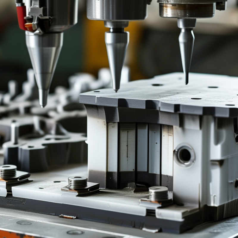
Define Part Requirements: Tolerance, Wall Thickness, and 2026 Volume
How to Choose the Right Injection Moulding Process in 2026?
Define Part Requirements: Tolerance, Wall Thickness, and 2026 Volume
Start with the part, not the machine. A 0.10 mm tolerance can increase tool finishing, inspection, and rejection risks. Confirm critical dimensions with functional testing, rather than applying tight tolerances everywhere. A neat spreadsheet can still lie.
Wall thickness controls filling, cooling, warpage, and cycle time. For many thermoplastic parts, designers often target roughly 1.5–3 mm walls, but resin, flow length, and geometry change the answer. Keep transitions gradual. Avoid sudden thick sections near ribs or bosses. Those areas may create sink marks. Moldflow simulation helps, but it is not a substitute for a physical trial.
Forecast 2026 demand in three ranges: prototypes, pilot batches, and repeat production. Low volume may justify a simpler aluminium tool or a flexible moulding route. Higher volume usually supports hardened tooling, automated handling, and shorter cycles. According to Grand View Research’s 2024 injection-moulded plastics analysis, the global market exceeded USD 260 billion in 2023, with continued growth expected through 2030. The Plastics Industry Association’s 2024 Size and Impact report also places United States plastics-industry shipments above USD 500 billion, showing why production scale deserves early attention.
Review the forecast again. Demand changes. Choose a process that meets today’s tolerance without making tomorrow’s volume unnecessarily expensive. That balance is often missed.
How to Choose the Right Injection Moulding Process in 2026? — Define Part Requirements: Tolerance, Wall Thickness, and 2026 Volume
| Injection Moulding Process | Typical Dimensional Tolerance | Recommended Wall Thickness | Indicative 2026 Annual Volume | Part Size and Design Profile | Best-Fit Applications | Key Trade-Offs |
|---|---|---|---|---|---|---|
| Standard Thermoplastic Injection Moulding | Approximately ±0.10–0.30 mm for a 100 mm feature, depending on resin, geometry, tool design, and process control. | Typically 1.5–4.0 mm; uniform walls are preferred to reduce sink marks, warpage, and voids. | About 5,000–1,000,000+ parts per year | Small to large rigid parts with repeatable geometry and moderate precision requirements. | Housings, covers, brackets, enclosures, consumer products, and general industrial components. | Requires mould investment; shrinkage and warpage must be managed through material selection, tooling, and cooling design. |
| Precision Injection Moulding | Approximately ±0.03–0.10 mm for a 100 mm feature under controlled conditions; tighter values require validation and may not apply to every feature. | Usually 1.0–3.0 mm, with highly consistent wall sections and carefully controlled mould temperature. | About 10,000–500,000 parts per year | Small to medium parts with tight fit, function, or dimensional repeatability requirements. | Precision gears, fluid-control components, optical supports, measurement parts, and close-fitting assemblies. | Higher tooling, inspection, and process-control costs; material shrinkage and thermal expansion remain important limitations. |
| Thin-Wall Injection Moulding | Approximately ±0.10–0.25 mm for a 100 mm feature, depending strongly on flow length, resin, and moulding conditions. | Commonly 0.5–1.5 mm; high flow speed, effective venting, and suitable resin grades are often required. | About 100,000–10,000,000+ parts per year | Lightweight, high-speed-cycle parts with short flow paths and carefully balanced wall sections. | Packaging components, disposable products, lightweight consumer parts, and high-volume electronic covers. | Limited process window, higher risk of short shots and warpage, and greater sensitivity to mould filling and cooling conditions. |
| Insert Moulding | Approximately ±0.10–0.30 mm for the moulded polymer features; insert position tolerance also depends on fixture accuracy. | Typically 1.5–4.0 mm around the insert, with adequate polymer coverage and draft for reliable encapsulation. | About 10,000–1,000,000 parts per year | Parts combining thermoplastics with metal, electronic, threaded, or preformed components. | Threaded bushes, electrical terminals, connectors, reinforcement parts, and structural assemblies. | Reduces secondary assembly but adds insert loading, alignment, handling, and quality-control requirements. |
| Two-Shot or Overmoulding | Approximately ±0.10–0.30 mm for polymer features; bonding and registration depend on material compatibility and tool accuracy. | Commonly 1.0–3.5 mm per material layer; the soft layer may be thinner when supported by a rigid substrate. | About 25,000–1,000,000 parts per year | Multi-material or multi-colour components requiring integrated soft-touch, sealing, grip, or visual features. | Seals, handles, grips, buttons, protective covers, and ergonomic assemblies. | Higher tooling complexity and validation effort; material bonding, shrinkage differences, and cycle time must be controlled. |
| Gas-Assist Injection Moulding | Approximately ±0.15–0.40 mm for major external features, depending on gas penetration, wall design, and process stability. | Polymer walls are commonly about 2.5–6.0 mm, with hollow gas channels used to reduce mass and sink marks. | About 25,000–500,000 parts per year | Large or thick structural parts where reduced weight, stiffness, and lower sink-mark risk are priorities. | Automotive-style handles, frames, appliance components, structural housings, and long beam-like parts. | Needs specialised gas equipment and tooling; internal gas channels and variable wall support require careful design. |
| Structural-Foam Injection Moulding | Approximately ±0.20–0.50 mm for a 100 mm feature, with lower dimensional precision than compact injection moulding. | Typically 3.0–10.0 mm or more, depending on density reduction, skin thickness, and structural requirements. | About 5,000–250,000 parts per year | Large, rigid parts where low weight, stiffness, and reduced material usage are more important than fine surface detail. | Machine housings, equipment panels, pallets, structural enclosures, and large industrial components. | Can reduce weight and clamping-force demand, but surfaces may show swirl, texture, or foam-related cosmetic variation. |
| Liquid Silicone Rubber Injection Moulding | Approximately ±0.10–0.30 mm, depending on geometry, mould construction, flash control, and post-curing requirements. | Commonly 0.5–4.0 mm; very thin sections require appropriate flow behaviour and balanced filling. | About 10,000–5,000,000 parts per year | Flexible, elastic, temperature-resistant, or chemically resistant parts with demanding sealing performance. | Gaskets, membranes, valves, medical-style components, seals, keypads, and protective covers. | Requires dedicated metering and moulding equipment; flash, venting, cure time, and material cleanliness are critical. |
| Prototype or Low-Volume Injection Moulding | Approximately ±0.15–0.40 mm for a 100 mm feature, depending on the mould material, tooling method, and number of cavities. | Typically 1.5–4.0 mm; draft and geometry may need adjustment to suit simplified tooling. | About 50–10,000 parts per year | Early production, market testing, engineering validation, and products with uncertain demand. | Pilot runs, design verification, pre-launch batches, replacement parts, and short product life cycles. | Lower initial tooling cost and faster launch are possible, but tool life, cycle time, automation, and repeatability may be limited. |
Note: The tolerance, wall-thickness, and volume figures are typical engineering planning ranges rather than guaranteed specifications. Final values should be confirmed through material data, mould-flow analysis, tolerance-stack analysis, tooling trials, and production validation.
Related Posts
-
How to Choose the Right Injection Moulding Process?
-
2026 How to Master Plastic Injection Molding Techniques?
-

2026 How to Master Injection Molding Techniques for Beginners?
-
Top 10 Injection Moulding Process Facts Every Buyer Should Know?
-
Exploring the Future of Injection Tooling Innovations and Trends
-
Top 10 Benefits of Injection Tooling You Need to Know About
Our Promise to You

Contact IPM
Phone: 937.898.3775
Fax: 937.535.0640
Email: sale@endtheplastic.com