What Are the Top Types of Precision Mold Components?
Precision Mold Components are the working parts that help a mold shape material, stay aligned, and release finished products consistently. Their dimensions may be small, but a slight mismatch can leave flash, uneven surfaces, or parts that stick during ejection. In a shop, these problems often show up as extra inspection, slower cycles, and repeated adjustments. The right component choices matter.
Common types include mold bases, core and cavity inserts, guide pins and bushings, ejector pins, and slides or lifters. Each has a distinct job. A guide pin keeps mold halves aligned as they close. An ejector pin pushes the molded part free, while a core forms internal features such as holes or ribs. Small details count. Surface finish, hardness, clearance, and wear resistance all affect performance.
This guide compares these component types and explains where each is commonly used. The best choice depends on the part geometry, material, expected production volume, and maintenance plan. A lifter may solve an undercut problem, for example, but it also adds motion and potential wear. There is no universal setup. Even familiar components can behave differently when tolerances, cooling, or lubrication change. Some selection decisions are less obvious than catalog descriptions suggest. Reviewing drawings with a mold designer or qualified supplier can help confirm fit, material, and operating requirements before production.
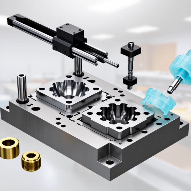
Precision Mold Components: Classification by Function and Mold Location
Precision Mold Components: Classification by Function and Mold Location
A practical way to classify precision mold components is to ask two questions: what does each part do, and where does it sit? Components near the cavity and core shape the product directly. Cavity inserts form outer surfaces, while core inserts create holes, ribs, and internal contours. Their fit affects dimensions and surface finish. Even a small mismatch can leave a visible seam.
At the parting line, alignment pins and bushings help the two mold halves meet consistently. Support pillars resist pressure behind the mold plates, while guide rails or wear plates control movement in sliding sections. These parts may not touch the molded product, but their wear can shift the cavity over time. That relationship is easy to overlook.
Ejection components sit behind or within the core. Ejector pins, sleeves, and blades push the cooled part free; their shape and placement should match the product’s geometry. Cooling channels and baffles manage heat inside the mold, while seals help prevent coolant leakage. Small parts matter. A useful classification should also note maintenance access, not just function or location. In real molds, categories overlap, and a component’s role may change with the design. That can make a neat chart less useful than a clear assembly drawing.
Top Types of Precision Mold Components
Classification by function and typical mold location
How to read this chart: Each bar counts the representative component examples listed for that function. These counts describe the examples shown, not market share or how often components are used.
Examples: Forming—cavity and core inserts; guiding—leader pins and guide bushings; ejection—ejector pins, sleeves, and blades; side-action—slides, angle pins, and lifters; cooling—baffles and bubblers; support and retention—support pillars, screws, and dowel pins.
Guide Pillars and Bushes: ISO 8694:1998 Alignment Components
Guide pillars and bushes keep mold halves aligned as they close under load. ISO 8694:1998 specifies dimensions for these alignment components used in tools. It supports consistent selection, but compliance alone cannot guarantee accurate molding. Fit, hardness, lubrication, and installation still matter. Small parts. Big consequences. A Fortune Business Insights report estimated the global mold market at USD 48.34 billion in 2023, forecasting USD 77.81 billion by 2032. That growth points to continued demand for dependable tooling, though market size does not measure component quality.
In practice, a pillar should enter its bush smoothly, without binding or noticeable lateral play. Excessive clearance can let the mold halves shift; too little may cause friction, heat, and wear. Check alignment after installation, and inspect contact surfaces for scoring or uneven polishing. A useful detail is often missed: poor lubrication can mimic a dimensional problem. I have seen teams replace parts before checking that simple cause. It is worth questioning the measurement setup, too.
Tip: Keep a record of running hours, lubrication, and wear measurements. Compare readings over time, not just against a single inspection. Replace matched components when wear compromises alignment, and verify the mold closes evenly before production resumes.
Core and Cavity Inserts: ASTM A681 Tool-Steel Classification
For core and cavity inserts, ASTM A681 offers a useful framework for identifying alloy tool steels. It classifies grades by type, such as A-series air-hardening, D-series high-carbon, high-chromium, H-series hot-work, and P-series mold steels. The grade name matters, but it does not tell the whole story. Heat-treatment condition, insert size, and machining history also affect performance.
P20 is commonly selected for mold inserts that need a practical balance of machinability and strength, often without extensive hardening after machining. For demanding thermal cycles, H13 may be considered for its hot-work properties and resistance to thermal fatigue. A2 or D2 can suit applications where wear resistance is a stronger concern, though their hardness may complicate machining and polishing. There is no universal winner. A mirror-finish cavity, for example, may need a different trade-off than a core exposed to abrasive resin.
Check the specified grade and condition against the steel supplier’s certification, then confirm hardness after heat treatment. Small details count. A sharp corner can concentrate stress, while uneven cooling may distort a thin insert. ASTM A681 helps establish the material category; it does not replace design checks or process validation. That distinction is easy to overlook.
Runner and Cooling Components: Material Flow and Heat-Removal Systems
Runner and Cooling Components: Material Flow and Heat-Removal Systems
Runner components guide molten plastic from the nozzle to each cavity. Their layout affects filling speed, pressure loss, and material waste. A balanced runner helps cavities fill more evenly, especially in multi-cavity molds. Cold runners also need practical ejection and trimming access. Small details matter. A narrow turn or rough surface can disturb flow, so designers should review both geometry and processing conditions.
Cooling components remove heat through channels, baffles, bubblers, and inserts. Channel placement should follow the part’s shape and thickness, not just the easiest route through the mold. Steel around a deep rib may retain heat, while a nearby channel can improve cooling consistency. But closer is not always better; insufficient steel can weaken the mold or cause leaks. A layout that looks balanced on screen may still behave unevenly in steel. Testing and measurement are essential.
Tips: Keep cooling channels clean and check water flow regularly. Compare temperatures across the mold, not at one convenient point. Record cycle changes during trials. One detail is easy to overlook: a blocked channel can resemble a process problem, so verify the cooling circuit before changing settings.
Ejector Pins and Sleeves: ISO 6751:2008 and ISO 6752:2008
Ejector pins and sleeves control how a molded part leaves the cavity, so small fit errors can mark parts or slow production. ISO 6751:2008 specifies cylindrical-head ejector pins; ISO 6752:2008 covers 30°-head ejector pins. Both help define consistent dimensions for pin selection and replacement. One important correction: these two standards address pins, not sleeves. ISO 8405 covers ejector sleeves. Check the current standard edition and the mold drawing before ordering; a familiar part name alone is not enough.
The scale of molding makes repeatability important. PlasticsEurope’s Plastics—The Fast Facts 2023 reports 400.3 million tonnes of global plastics production in 2022. That figure is not a measure of mold-component demand, but it shows the breadth of production where reliable ejection matters. In a tool, inspect pin straightness, sliding clearance, and the contact face; for sleeves, check concentricity around the core pin and look for burrs near the tip. Fit matters. Too much clearance can leave flash or witness marks, while insufficient clearance may cause sticking, especially as the tool warms. Standards help narrow choices, but they do not replace trial runs. I have seen teams check nominal dimensions and overlook hot operating conditions. That is an easy mistake to repeat.
What Are the Top Types of Precision Mold Components? - Ejector Pins and Sleeves: ISO 6751:2008 and ISO 6752:2008
| Component type | Typical design or feature | Common mold application | Relevant standard information | Selection considerations |
| Cylindrical-head ejector pin | Straight pin with a cylindrical head; the head bears against the ejector plate. | General-purpose ejection of molded parts from cores and mold cavities. | ISO 6751:2008 specifies ejector pins with cylindrical heads for injection moulds. | Check pin diameter, working length, head geometry, fit, material, and operating temperature against the mold design. |
| 30° tapered-head ejector pin | Pin with a tapered head designed to seat in the corresponding ejector-plate arrangement. | Molds designed for a tapered-head pin and matching plate geometry. | ISO 6752:2008 specifies ejector pins with 30° tapered heads for injection moulds. | Confirm the specified head angle and matching seat; do not substitute for a cylindrical-head pin without checking the design. |
| Ejector sleeve | Hollow, tube-shaped ejector that pushes around a core pin or core feature. | Ejection around cylindrical or annular features, such as bosses and tubular sections. | ISO 6751 and ISO 6752 cover ejector pins, not ejector sleeves. Specify sleeve dimensions and tolerances from the applicable sleeve specification or mold drawing. | Check inside and outside diameters, wall thickness, length, guidance, clearance, and alignment with the core. |
| Stepped or shouldered ejector pin | Pin with a change in diameter or a shoulder to suit a specific mold layout. | Custom ejection points where a standard straight pin does not suit the available space or support arrangement. | Treat as a design-specific component; confirm any applicable standard dimensions with the supplier or mold documentation. | Review shoulder position, guide length, load support, fit, and risk of bending or binding. |
| Flat ejector pin | Pin with a flat or blade-like working section rather than a fully round cross-section. | Thin ribs, narrow features, or locations where a round pin cannot provide suitable contact. | Confirm the component geometry and tolerances from the mold drawing; ISO 6751 and ISO 6752 identify specific head styles, not every pin shape. | Check orientation, bearing area, cavity clearance, and resistance to twisting or wear. |
Standards note: ISO 6751:2008 and ISO 6752:2008 describe different ejector-pin head designs. They should not be read as ejector-sleeve standards. Confirm the required edition, dimensions, tolerances, and component compatibility against the mold drawing and the applicable standard before ordering.